
Set up your 3dBi-antenna ESP32 in minutes
The "U" in WROOM-32U means a U.FL connector for an external antenna — giving you roughly +20 dBm of usable signal over standard PCB-antenna boards. Perfect for ESPresense, Home Assistant, BLE tracking, and smart-home gateways that need to reach across the house.
First: Confirm This Is the Right Board
Three things customers commonly mistake. Check each one before plugging in.
USB Port: Check Your Variant
We sell two versions of the ESP32-WROOM-32U: one with a Micro USB port (trapezoid-shaped) and one with USB-C (oval, reversible). Confirm which one you ordered, then use a matching data cable — not a charge-only one. No cable is included in the box.
Antenna: U.FL / IPEX
Look for a small gold-colored U.FL socket on the metal shield instead of the wavy PCB antenna trace. The included 3dBi external antenna screws onto the SMA pigtail. Always install before powering on.
Pin Labels: Printed on PCB
GPIO numbers are silk-screened next to each pin on the board, so you can wire most projects without needing the diagram in front of you. A few pin positions differ slightly from other vendors' generic ESP32 boards — double-check the diagram below if you're following a tutorial written for a different board.
Install the Antenna First
Do This Before Powering On
The ESP32-WROOM-32U ships with the antenna detached. Powering the radio without an antenna can damage the RF stage over time, and Wi-Fi will be effectively useless. Take 30 seconds to attach it correctly:
Antenna installation:
- Locate the small U.FL socket on the metal shield (or the SMA pigtail already attached at the factory).
- If using the U.FL pigtail: align it flat over the socket and press straight down with your fingernail until you feel a click. Don't rock it side-to-side — you'll bend the pin.
- Hand-thread the 3dBi antenna onto the SMA connector. Finger-tight only; pliers will strip the threads.
- Orient the antenna vertically for omnidirectional coverage.
Inspect the board first. If you see bent header pins from shipping, gently straighten them with needle-nose pliers before plugging into a breadboard or USB.
Signal Comparison
Pick a distance to compare typical RSSI readings.
Arduino IDE Setup in 4 Steps
From a blank Arduino IDE to your first upload — about 5 minutes.
Install the CP210x driver
The -32U uses the Silicon Labs CP210x USB-to-UART bridge. Most modern Windows 10/11 and macOS releases install it automatically. On Linux it ships with the kernel. If your computer doesn't see a new COM port, install the driver manually:
silabs.com/developers/usb-to-uart-bridge-vcp-driversAdd the ESP32 board manager URL
In the Arduino IDE, open File → Preferences. Paste the URL below into "Additional Board Manager URLs".
Install the ESP32 package
Open Tools → Board → Boards Manager. Search for
"esp32" and install "esp32 by Espressif Systems".
ESP-IDF users can skip this and go straight to idf.py.
Pick the board & port
ImportantUnder Tools → Board → ESP32 Arduino, choose "NodeMCU-32S" — this is the correct profile for the ESP32-WROOM-32U dev board.
Then under Tools → Port, select the COM port that appeared
(e.g. COM5 on Windows, /dev/cu.SLAB_USBtoUART on macOS,
/dev/ttyUSB0 on Linux).
When Upload Fails: the BOOT Button
Manual Override
In normal use, you just click Upload and the board flashes itself — no
buttons needed. If the upload stalls with Connecting......_____, the chip didn't
enter download mode automatically. The fix is simple: hold the BOOT button
(also labeled FLASH) while the upload is connecting, then release. You don't need
to press EN, RST, or any other button.
If "Connecting......" appears:
- Click Upload in the Arduino IDE
- Wait for
Connecting......in the console - Press and hold BOOT on the board
- Once you see
Writing at 0x..., release BOOT
What's actually going wrong?
Before opening a return, look at where -32U issues actually come from. Genuine hardware failures are rare — the chart below reflects what we see in real support cases.
Estimated probability based on customer support cases.
CP210x Driver Missing (35%)
COM port never appears in Device Manager / ls /dev/cu.*. Install the
Silicon Labs CP210x VCP driver manually, then unplug and re-plug.
Wrong USB Cable (25%)
Confirm your variant first — we sell both Micro USB and USB-C versions. Either way, the cable from your drawer might be charge-only. Use a known data cable.
Antenna Not Attached (15%)
Wi-Fi scans return nothing or RSSI is worse than a phone in the same spot. Check the U.FL connector clicked in fully and the SMA antenna is screwed on snugly.
Wrong Board Profile (15%)
Sketch compiles for AVR or for the wrong ESP32 variant. Pick "NodeMCU-32S" under Tools → Board → ESP32 Arduino and verify the COM port.
Physical Damage in Transit (10%)
Bent header pins, cracked Micro USB shroud, or a U.FL pin pushed sideways. Inspect the board the moment you open the anti-static bag — bent pins straighten back with needle-nose pliers, but a cracked USB port needs a replacement. Contact us through your order if you find shipping damage.
Interactive Troubleshooter
Tell us what's happening — we'll narrow it down.
What's the symptom?
Pinout Quick Reference
GPIO labels are silk-screened on the -32U PCB, so you can wire most projects directly. Keep the diagram below handy when following tutorials written for other vendors' ESP32 boards — a few pin positions differ.
ESP-WROOM-32U · 30-Pin Layout
External-antenna variant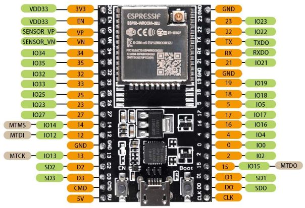
Dual-core 240 MHz with four input-only pins (GPIO 34, 35, 36/VP, 39/VN), two DAC outputs (GPIO 25, 26), I²C on GPIO 21/22, and VSPI on GPIO 5/18/19/23. The pins labeled SD2, SD3, CMD, CLK, D0, D1 are wired to the internal SPI flash — do not connect anything to them. JTAG is exposed on MTMS/MTDI/MTCK/MTDO (GPIO 14/12/13/15).
Module Specifications
3.3 V GPIO Warning
ESP32 GPIOs are not 5 V tolerant. Connecting a 5 V signal (Arduino Uno output, HC-SR04 echo pin, an unshifted level converter) directly to a GPIO will permanently damage the chip. Use a level shifter or voltage divider for 5 V devices.
The "Sanity Check" List
Run through these before opening a return on Amazon.
Inspect for shipping damage
Before plugging in, look at the header pins (any bent?), the Micro USB shroud (cracked?), and the U.FL connector (sideways pin?). Straighten bent pins gently with needle-nose pliers before pressing into a breadboard.
Attach the antenna before powering
Snap the U.FL pigtail straight down onto the socket, then hand-tighten the 3dBi antenna on the SMA end. Running the radio without an antenna stresses the RF stage.
Use the right USB data cable
Match your variant: Micro USB or USB-C. Either way, confirm the cable transfers data — the kind that lets a phone show up as a drive on your PC. Charge-only cables are the #1 cause of "no COM port" reports.
Confirm the COM port appears
Windows: Device Manager → Ports (COM & LPT) → Silicon Labs CP210x.
macOS: ls /dev/cu.SLAB_USBtoUART*. Linux: dmesg | grep cp210x.
If missing, install the driver.
Hold BOOT during upload (if needed)
Click Upload, wait for Connecting......, then hold BOOT until
the chip starts writing. If the upload now succeeds, the board is fine — auto-reset
just isn't working with your USB hub or cable.
Verify Wi-Fi range with WiFiScan
Run the File → Examples → WiFi → WiFiScan sketch. RSSI values should be roughly 15–20 dBm stronger than a PCB-antenna board in the same spot. If they're the same or weaker, the antenna isn't connected properly.