
Got an ESP32 that won't cooperate?
Take a breath. Every board is bench-tested before it ships from our warehouse, and the vast majority of "broken" ESP32 modules turn out to be a missing driver, the wrong board profile, or a charge-only USB cable.
Arduino IDE Setup in 4 Steps
From a blank Arduino IDE to your first "Hello, ESP32" upload — about 5 minutes.
Install the CP2102 driver
Plug the board into a USB port. Open Device Manager (Windows) or System Information → USB (macOS). If you see "CP2102 USB to UART Bridge" listed, you're done. If it shows up with a yellow warning icon, install the driver manually:
silabs.com/developers/usb-to-uart-bridge-vcp-driversAdd the ESP32 board manager URL
In the Arduino IDE, open File → Preferences. Paste the URL below into "Additional Board Manager URLs". If multiple URLs are already there, separate them with commas.
Install the ESP32 package
Open Tools → Board → Boards Manager (or click the second icon in the left sidebar of the IDE 2.x). Search for "esp32" and install "esp32 by Espressif Systems".
Pick the board & port
ImportantUnder Tools → Board → ESP32 Arduino, choose "NodeMCU-32S" — this is the correct profile for the ESP-WROOM-32 dev board.
Then under Tools → Port, select the COM port that appeared when you
plugged the board in (e.g. COM5 on Windows,
/dev/cu.SLAB_USBtoUART on macOS, /dev/ttyUSB0 on Linux).
LED_BUILTIN to GPIO 2, and hit Upload. In most cases the board auto-resets and
flashes on its own — if it doesn't, see the BOOT button section below.
When Upload Fails: the BOOT Button
Manual Override
In normal use, you just click Upload in the Arduino IDE and the
board flashes itself — no buttons needed. If the upload stalls with
Connecting......_____, the chip didn't enter download mode automatically.
The fix is simple: hold the BOOT button (also labeled FLASH)
while the upload is connecting, then release. You don't need to press EN, RST, or any other button.
If "Connecting......" appears:
- Click Upload in the Arduino IDE
- Wait for
Connecting......to print in the console - Press and hold BOOT on the board
- Once you see
Writing at 0x..., release BOOT
Try the simulator on the right to see how it behaves with and without holding BOOT.
What's actually going wrong?
Before opening a return ticket, look at where ESP32 issues actually come from. Real hardware failures are rare — the chart below reflects what we see in real support cases.
Estimated probability based on customer support cases.
CP2102 Driver Missing (40%)
Windows 10/11 and macOS usually grab the driver automatically, but on older systems or stripped-down Windows installs the COM port never appears. Install the Silicon Labs CP2102 VCP driver manually to fix this.
Charge-Only USB Cable (30%)
The cable that came with your phone charger often has only the power wires connected. Use a known data cable — the kind that lets your phone show up as a drive when plugged into your PC.
Wrong Board Profile (20%)
Sketch compiles for AVR or for the wrong ESP32 variant. Pick "NodeMCU-32S" under Tools → Board → ESP32 Arduino, and double-check the COM port.
Actual Hardware Issue (10%)
Static damage, over-voltage on a 3.3 V GPIO, or a board damaged in transit. Genuine factory defects are uncommon — but if every step below fails, contact us.
Interactive Troubleshooter
Tell us what's happening — we'll narrow it down.
When you plug the board in, what happens?
Pinout Quick Reference
Two common form factors ship from our warehouse. Confirm yours by counting the header pins (19 per side = 38-pin, 15 per side = 30-pin).
ESP-WROOM-32 · 38-Pin Dev Board
Most common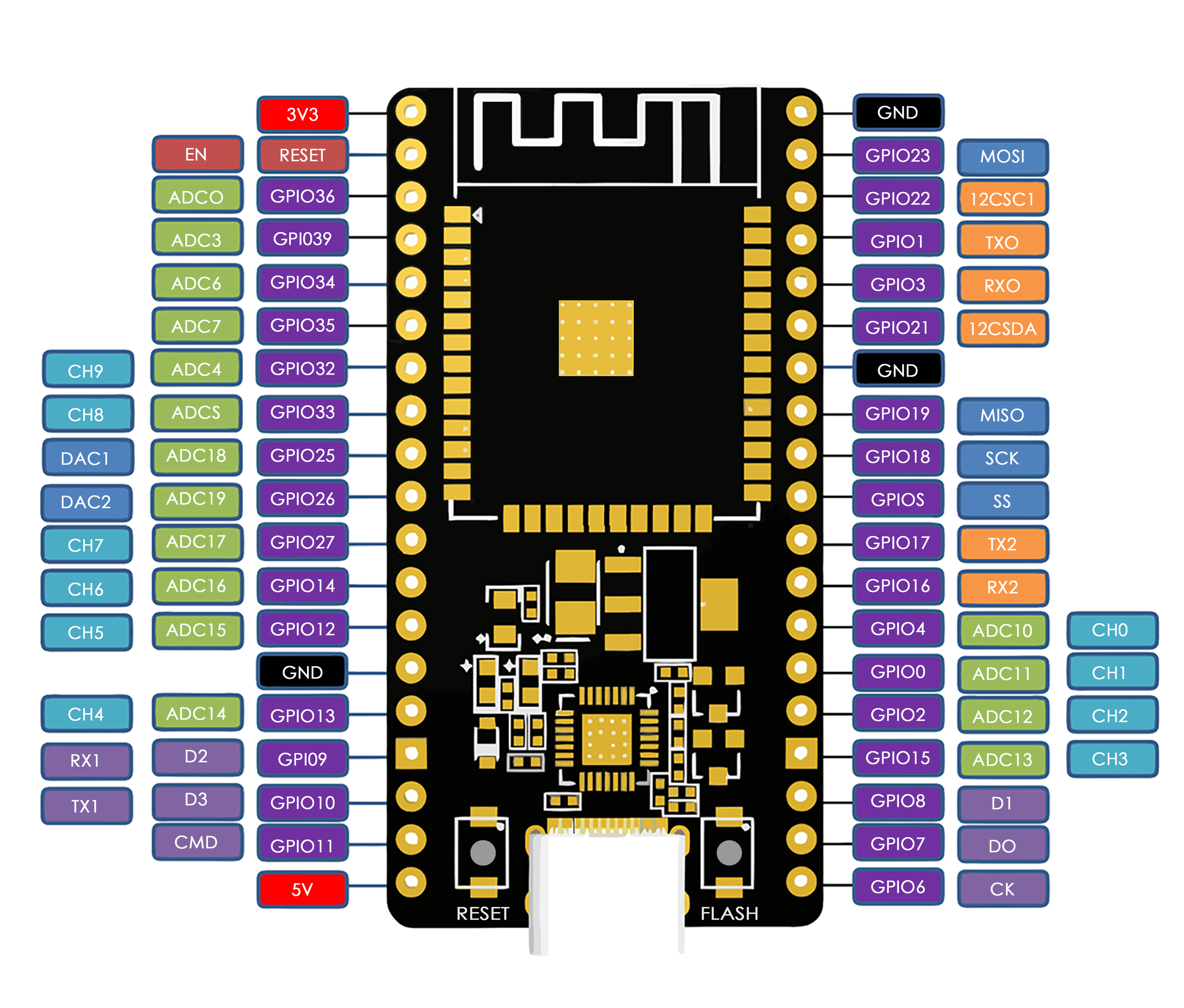
Wider PCB. Exposes every usable GPIO, including the four input-only pins (GPIO 34, 35, 36/VP, 39/VN) and the two DAC outputs (GPIO 25, 26). Recommended when you need lots of analog or sensor inputs. The pins labeled GPIO 6–11 are wired to the internal SPI flash — do not connect anything to them.
ESP-WROOM-32 · 30-Pin Dev Board
Compact / breadboard friendly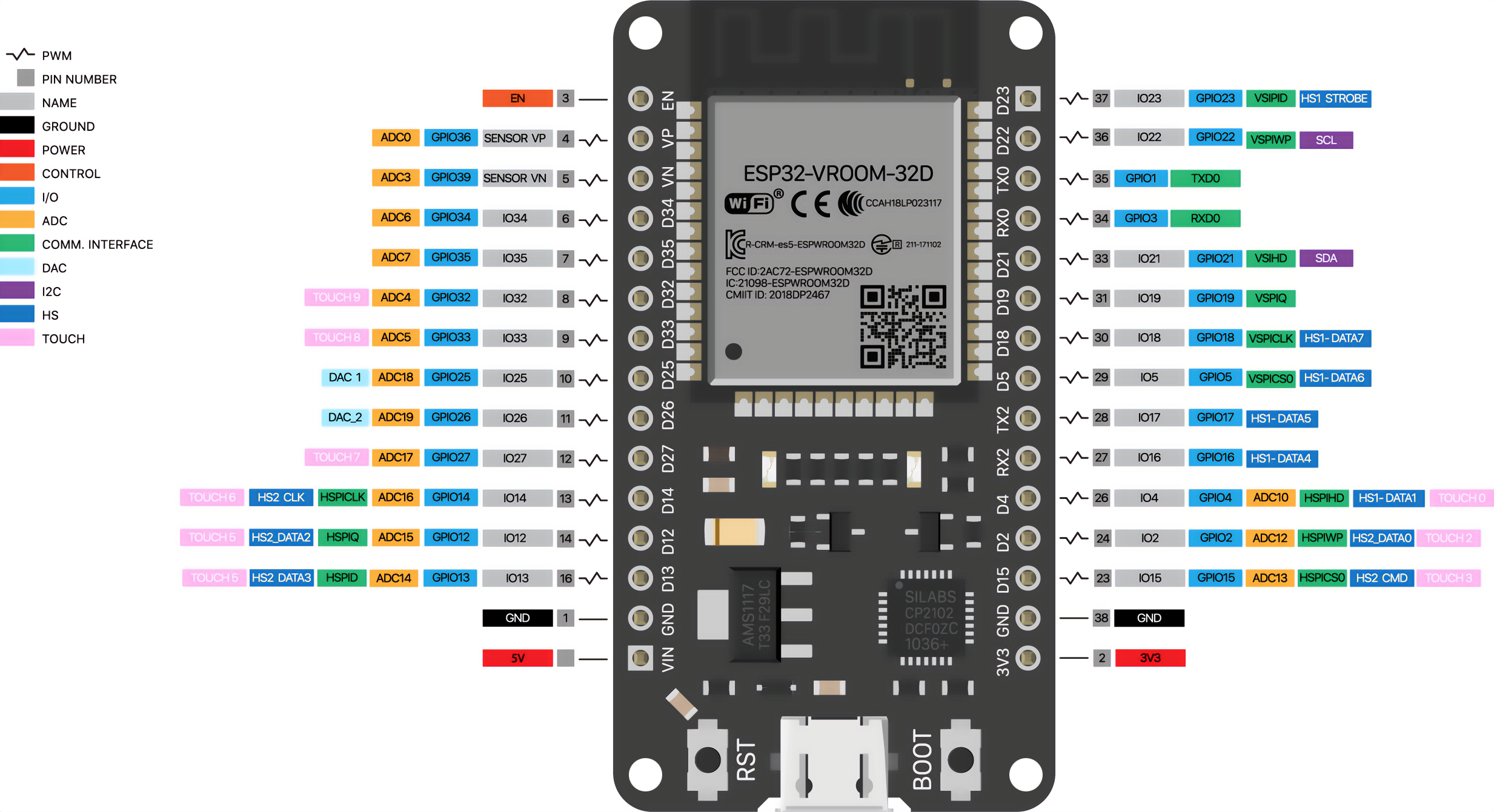
Slimmer PCB — fits a standard breadboard with rows free on each side for jumper wires. Hides the GPIO 6–11 flash pins (which you can't use anyway), but still exposes every common peripheral: I²C (GPIO 21/22), VSPI (GPIO 5/18/19/23), UART, the input-only pins, and both DACs.
Module Specifications
3.3 V GPIO Warning
ESP32 GPIOs are not 5 V tolerant. Connecting a 5 V signal (Arduino Uno output, HC-SR04 echo pin, an unshifted level converter) directly to a GPIO will permanently damage the chip. Use a level shifter or voltage divider for 5 V devices.
The "Sanity Check" List
Run through these before opening a return on Amazon.
Swap the USB cable
Replace the cable with one you've used to transfer files from a phone or another microcontroller. Charge-only cables are the #1 cause of the "no COM port" complaint.
Confirm the COM port shows up
On Windows, open Device Manager and look under "Ports (COM & LPT)" for
Silicon Labs CP210x. On macOS, run ls /dev/cu.* in Terminal.
If it's missing, install the CP2102 driver.
Hold BOOT during upload
Click Upload, wait for Connecting...... in the IDE console, then press and hold
BOOT until the chip starts writing. If the upload now succeeds, the board is fine
— auto-reset just isn't working with your USB hub or cable.
Try a second computer
USB hubs, low-power laptop ports, and corporate machines with locked-down drivers cause mysterious failures. Plug directly into a desktop's rear USB port or try a different machine before concluding the board is bad.
Disconnect everything from the GPIOs
Sensors, displays, or motor drivers wired to the wrong pins (especially GPIO 0, 2, 12, 15) can block boot or trick esptool. Unplug everything except the USB cable, then try again.