
ESP32-S3
Super Mini
A dual-core 240 MHz powerhouse with Wi-Fi 4, Bluetooth 5 (LE), and native USB-C — all packed into an ultra-compact 22.5 × 18 mm castellated module.
Chip
ESP32-S3FH4R2 — Xtensa® dual-core 32-bit LX7
Supports AI acceleration • AES-128/256 • RSA • HMAC
Arduino IDE Setup
From a fresh IDE install to your first successful upload — about 5 minutes.
Add the Espressif Board Manager URL
In Arduino IDE go to File → Preferences. Paste the URL below into "Additional Boards Manager URLs". Separate multiple entries with commas.
Install the ESP32 Package
Go to Tools → Board → Boards Manager. Search for "esp32" and install "esp32 by Espressif Systems" (v2.x or later recommended).
Select Board & Configure Settings
Go to Tools → Board → ESP32 Arduino and choose "Waveshare ESP32-S3-Zero", then apply these settings:
Select the COM Port
Go to Tools → Port and select the port that appeared when you plugged in the board:
- 📺 Windows:
COM3,COM4… (check Device Manager) - 🍎 macOS:
/dev/cu.usbmodem... - 🐧 Linux:
/dev/ttyACM0or/dev/ttyUSB0
First Upload & BOOT Button
Click Upload (▲). If the upload stalls at Connecting...:
- Press and hold BOOT
- Press RESET once
- Release BOOT when upload begins
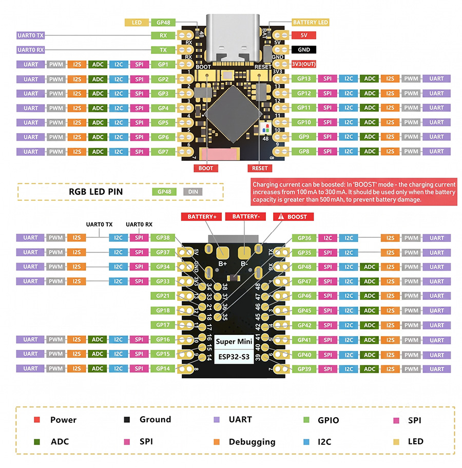
Pinout Diagram
Click the image to open the full-resolution pinout.
Power Pins
5V— USB power input3V3— 3.3V output (LDO regulated)GND— Ground reference
GPIO / ADC
- GP1–GP14 support 12-bit ADC (3.3V max)
- All GPIOs are 3.3V logic
- Most pins support PWM output
I²C / SPI / UART
- Flexible remappable peripherals
- Default I2C: SDA=GPIO8, SCL=GPIO9
- Default UART: TX=GPIO43, RX=GPIO44
⚠ GPIO 48 — WS2812 RGB LED & Power LED (Shared)
GPIO 48 drives both the red power indicator LED and the onboard WS2812 RGB LED. Use a dedicated NeoPixel library (FastLED or Adafruit NeoPixel) to control it — avoid digitalWrite(48, …) as it conflicts with the WS2812 data protocol.
3.3V GPIO — Not 5V Tolerant
Connecting 5V signals (Arduino Uno outputs, HC-SR04 echo, etc.) directly to any GPIO will permanently damage the chip. Use a logic-level shifter or voltage divider.
Wi-Fi Network Scanner
Your first program — lists all visible Wi-Fi networks in the Serial Monitor.
// ESP32-S3 Super Mini – Wi-Fi Network Scanner
// Requires: "USB CDC On Boot" = Enabled in Arduino IDE Tools menu

#include "WiFi.h"

void setup() {
  // Native USB CDC serial – give the port 2 s to open
  Serial.begin(115200);
  delay(2000);

  // Put radio in station mode and disconnect any saved AP
  WiFi.mode(WIFI_STA);
  WiFi.disconnect();
  delay(100);

  Serial.println("ESP32-S3 Super Mini ready.");
  Serial.println("Starting Wi-Fi scan...");
}

void loop() {
  Serial.println("\\nScanning…");

  int n = WiFi.scanNetworks();   // returns number of networks found

  if (n == 0) {
    Serial.println("No networks found.");
  } else {
    Serial.print(n);
    Serial.println(" networks found:");
    Serial.println("--------------------------------------------");

    for (int i = 0; i < n; i++) {
      Serial.printf("%2d | %-32s | %4d dBm | %s\\n",
        i + 1,
        WiFi.SSID(i).c_str(),
        WiFi.RSSI(i),
        (WiFi.encryptionType(i) == WIFI_AUTH_OPEN) ? "Open" : "Secured"
      );
      delay(5);
    }
    Serial.println("--------------------------------------------");
  }

  WiFi.scanDelete();   // free memory before next scan
  Serial.println("Next scan in 10 seconds…");
  delay(10000);
}
115200): 1 | MyHomeNetwork | -45 dBm | Secured
2 | Neighbor_5G | -72 dBm | Secured
3 | PublicHotspot | -81 dBm | Open
Common Issues & Fixes
Most problems have simple software causes. Check these first before assuming hardware failure.
Root cause: The ESP32-S3 uses a native USB CDC serial port — not a dedicated UART chip like CP2102. If USB CDC On Boot is disabled in the Tools menu, the USB serial connection is never initialized and Serial.print() is silently discarded.
Fix: In Tools, set USB CDC On Boot → Enabled, then re-upload your sketch.
Also check: Use a data-capable USB-C cable (not a charge-only cable). Set the Serial Monitor baud rate to 115200. Add a delay(2000) at the start of setup() to give the port time to enumerate.
The board has not entered download/boot mode. Follow this sequence:
- Click Upload in the Arduino IDE
- When you see
Connecting…, press & hold BOOT - Press RESET once (while still holding BOOT)
- Release BOOT — the upload should start immediately
Alternative: Try a different USB cable or USB port. Avoid USB hubs when flashing for the first time.
#1 — Charge-only cable: Phone charger cables often have only power wires. Swap for a cable that you have successfully used for data transfer.
#2 — Try a different USB port: Some front-panel USB ports deliver less power. Try a rear motherboard USB port directly.
#3 — Manual boot mode: Hold BOOT, plug in USB-C, then release BOOT. The board should appear as a port even without firmware.
#4 — macOS / Linux permissions: On Linux add yourself to the dialout group: sudo usermod -a -G dialout $USER, then log out and back in.
The WS2812 RGB LED and the red power LED both share GPIO 48. Using digitalWrite() on GPIO 48 corrupts the WS2812 timing signal.
Fix: Use FastLED or Adafruit NeoPixel library exclusively on GPIO 48. Example with FastLED:
#include <FastLED.h>
CRGB leds[1];
void setup() {
  FastLED.addLeds<WS2812, 48, GRB>(leds, 1);
  leds[0] = CRGB::Blue;
  FastLED.show();
}
Underpowered supply: Wi-Fi transmission peaks can draw ~300mA. A weak USB cable or hub cannot sustain this. Use a quality cable directly to a powered USB 3.0 port or add a 100µF capacitor between 3V3 and GND.
External loads: Servo motors or large LED arrays should be powered from an external 5V supply — not from the board's 3V3 pin.
Software: If the Serial Monitor shows Brownout detector was triggered, add a delay after Wi-Fi initialization: delay(500).
Technical Specifications
| Chip | ESP32-S3FH4R2 (Espressif) |
|---|---|
| Architecture | Xtensa® 32-bit LX7 dual-core |
| Clock Speed | Up to 240 MHz |
| SRAM | 512 KB internal SRAM + 384 KB ROM |
| Flash | 4 MB onboard SPI Flash |
| Wi-Fi | 802.11 b/g/n • 2.4 GHz • Up to 150 Mbps |
| Bluetooth | BT 5.0 (LE) • Long Range • Mesh support |
| USB | USB-C • Native USB 2.0 (OTG capable) • No bridge chip |
| Operating Voltage | 3.3 V logic • 5 V input via USB-C |
| Deep Sleep | ~43 µA |
| Antenna | Onboard PCB ceramic antenna |
| Onboard LEDs | Red power indicator + WS2812 RGB LED (both on GPIO 48) |
| Buttons | BOOT • RESET |
| Dimensions | 22.52 × 18 mm • Castellated half-holes |
Sanity Check
Run through these before concluding the board is defective. Check off each item.
Use a data-capable USB-C cable
Charge-only cables have no data wires. Try a cable proven to work with another device for data transfer.
Set "USB CDC On Boot" to Enabled
This is the #1 reason Serial Monitor is blank. Re-upload after changing this setting.
Select board "Waveshare ESP32-S3-Zero"
Generic ESP32 or ESP32-S2 profiles will fail to compile or produce incorrect pin assignments.
Confirm the COM port appears
On Windows: Device Manager → Ports. On macOS: ls /dev/cu.*. No port = cable or mode issue.
Try BOOT + RESET if upload hangs
Hold BOOT, tap RESET, release BOOT once upload starts. Works every time.
Disconnect all GPIO peripherals
Sensors or displays on the wrong pin can block boot. Strip back to bare board + USB for debugging.